Mfr Part # 28009
EXPERIENTIAL ROBOTICS PLATFORM (
SparkFun Electronics
License: Attribution Robot Kits Serial / UART Wifi ESP32 Raspberry Pi MCU XIAO
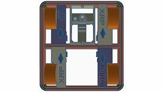
The XRP (Experiential Robotics Platform) is an affordable educational robot developed through a broad consortium of educational and industry partners. The controller features an RP2350 microcontroller, which is the same chip found in the Raspberry Pi Pico 2. It comes equipped with motors, encoders, a rangefinder, an IMU, and line-following sensors.
The XRP also features the same wireless module found on the Raspberry Pi Pico 2W, so wireless connectivity is technically available on the hardware. ESPHome currently does not support the RP2350, which means that using this radio would likely require MQTT. However, MQTT is a much slower protocol with more overhead compared to the native API of ESPHome. This trade-off is not suitable for real-time robot control, as a single command could take a hundred milliseconds or more to be transmitted and executed. To address this issue, I used a Seeed Studio XIAO ESP32-C3 as a dedicated UART bridge running ESPHome, which allows us to use the low-latency native API.
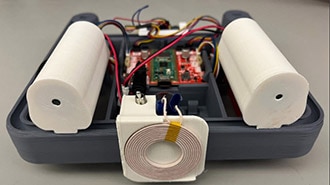
This build was originally created as a demonstration unit for us at DigiKey to showcase the XRP remotely while at tradeshows and events. As such, the images in this guide show the robot with a power cable tether; however, the XRP is fully capable of battery operation, and if you intend to run it untethered, you may want to look at adding charging capability. To help with that, check out the resources in the "Going Further" section at the end of this post.
The finished system provides:
Hold-to-drive directional buttons with automatic safety timeouts
Speed control (0-100%) and servo arm position (0-180°) sliders
Live sensor feeds: distance, battery voltage, IMU accelerometer (X/Y/Z), line sensors, and motor encoders
The project has three layers:
XRP (RP2350/MicroPython): Runs the robot. Listens for commands over UART and streams sensor data back.
xrp-bridge (XIAO ESP32-C3/ESPHome): Functions as a transparent serial-to-WiFi bridge, allowing control buttons and sliders, and sensor data to be exposed to Home Assistant via the ESPHome native API.
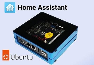
Home Assistant: Hosts the dashboard and automations that translate button presses into a continuous command stream with safety watchdogs.
This guide assumes you already have:
Home Assistant installed and running
The ESPHome integration installed in Home Assistant
Basic familiarity with the ESPHome web dashboard (flashing firmware, editing YAML)
The XRP robot assembled and working
A browser-based connection to https://xrpcode.wpi.edu for uploading files to the XRP
You will also need a soldering iron, solder, and a USB cable for flashing the XIAO and XRP.
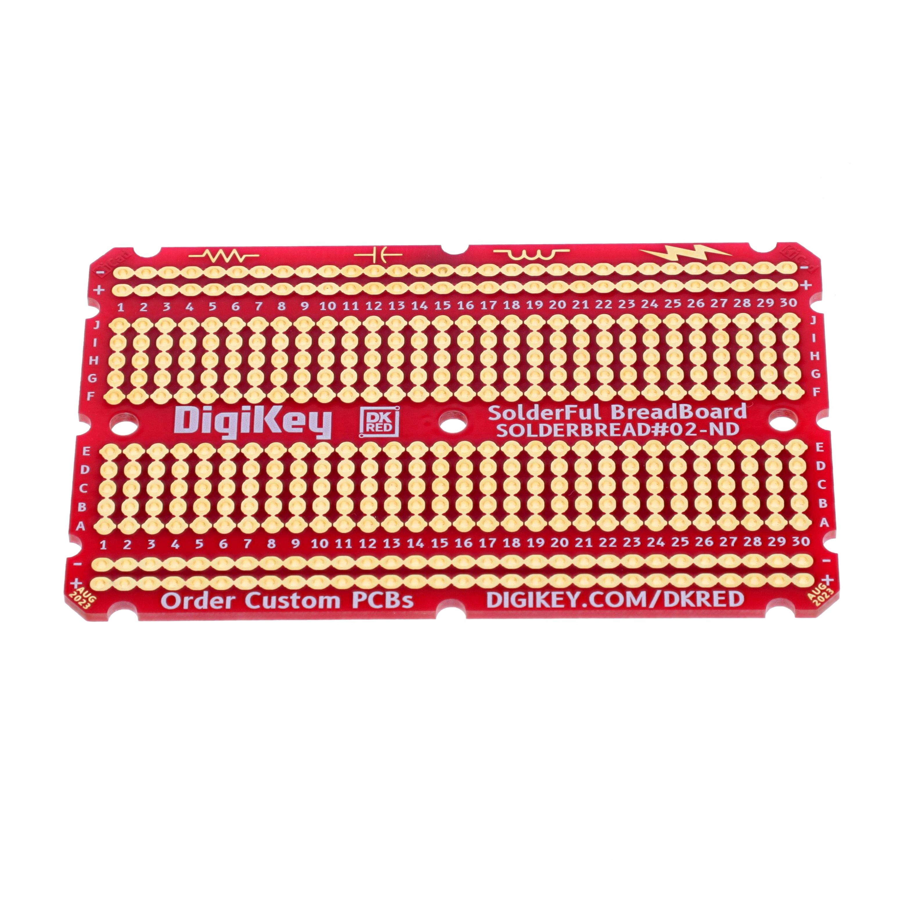
The XIAO ESP32-C3 mounts directly onto the XRP controller board's expansion header using the perfboard as an adapter. The perfboard serves two purposes: it provides the XIAO with a socketed, removable mount, and it carries the four wires (5V, GND, TX, RX) needed to connect the two microcontrollers.
The XIAO is powered from the XRP's 5V servo power pin:
XRP Servo Power (5V) → XIAO VUSB
XRP GND → XIAO GND
UART communication is on the following pins:
XRP GPIO 16 (TX) → XIAO GPIO 20 / D7 (RX)
XRP GPIO 17 (RX) → XIAO GPIO 21 / D6 (TX)
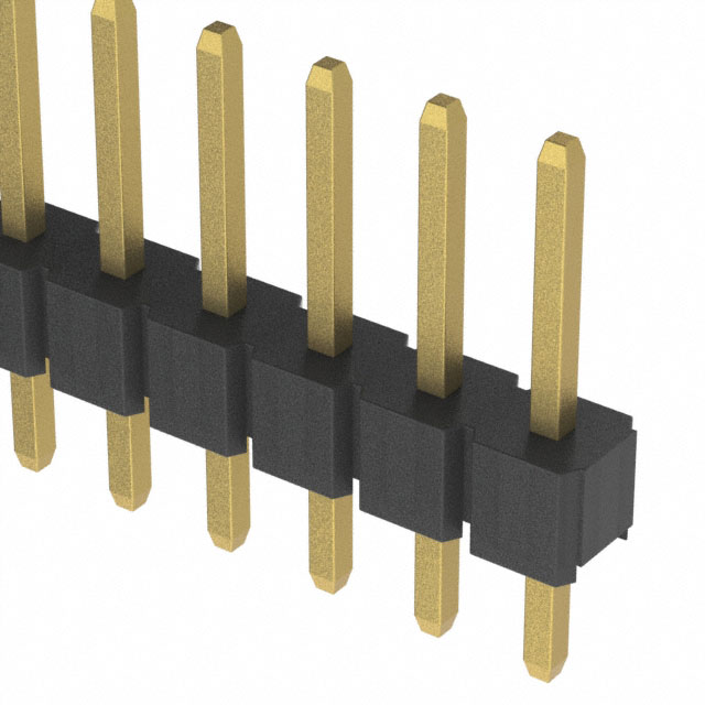
Solder female headers onto the perfboard at the XIAO pin positions. This lets you remove the XIAO for reprogramming without desoldering.
Solder male headers onto the bottom of the perfboard to match the female headers on the XRP controller board.
Run short wire jumpers on the perfboard to connect the four required signals: 3.3V, GND, TX, and RX as listed above.
The xrp-bridge firmware turns the XIAO ESP32-C3 into a connected UART bridge. It handles all serial I/O with the XRP, parses incoming sensor data, exposes control entities to Home Assistant, and enforces baud rate and logging settings.
ESPHome logging is redirected away from UART (baud_rate: 0) so it does not interfere with XRP communication.
The UART is configured for 115200 baud — matching the XRP MicroPython code.
Sensor values are filtered with a sliding window moving average plus a delta filter to smooth out noise and reduce unnecessary HA state updates.
A custom HA service (send_command) is included for debugging. This allows you to send raw commands to the XRP from the HA developer tools.
In the ESPHome dashboard, create a new device and select the Seeed XIAO ESP32-C3 as the board.
Replace the generated YAML entirely with the configuration provided below
Edit the wifi section with your network credentials, or ensure they are defined in your secrets.yaml.
Connect the XIAO to your computer via USB (before installing it on the perfboard adapter) and click Install.
Once flashing succeeds, and after adoption in Home Assistant, the xrp-bridge device will expose these entities:
sensor.xrp_bridge_distance (cm, displayed as inches in US locale)
sensor.xrp_bridge_battery_voltage (V)
sensor.xrp_bridge_imu_accel_x/y/z (m/s²)
sensor.xrp_bridge_left_line_sensor (0–1023)
sensor.xrp_bridge_right_line_sensor (0–1023)
sensor.xrp_bridge_left_encoder (counts, signed)
sensor.xrp_bridge_right_encoder (counts, signed)
number.xrp_bridge_robot_speed (0–100%)
number.xrp_bridge_arm_position (0–180°)
button.xrp_bridge_forward/reverse/left/right/stop
With the XIAO flashed and adopted, disconnect the USB cable and install the XIAO on the adapter board, but don’t connect it to the XRP yet.
ESPHome XRP bridge configuration:
esphome:
  name: xrp-bridge
  friendly_name: XRP Bridge

esp32:
  board: seeed_xiao_esp32c3
  variant: esp32c3
  framework:
    type: esp-idf

# Enable logging
logger:
  level: DEBUG
  baud_rate: 0  # Disable logging via UART to avoid conflicts

# Enable Home Assistant API
api:
  encryption:
    key: "YOUR_ENCRYPTION_KEY_HERE”
  reboot_timeout:
    minutes: 2
  services:
    # Custom service for raw commands (great for debugging!)
    - service: send_command
      variables:
        command: string
      then:
        - uart.write:
            id: xrp_uart
            data: !lambda |-
              std::string cmd = command + "\n";
              return std::vector<uint8_t>(cmd.begin(), cmd.end());
        - text_sensor.template.publish:
            id: last_command
            state: !lambda 'return command;'
        - logger.log:
            format: "Sent command to XRP: %s"
            args: ['command.c_str()']

ota:
  - platform: esphome
    password: "YOUR_OTA_PASSWORD_HERE"

wifi:
  ssid: !secret wifi_ssid
  password: !secret wifi_password

  # Enable fallback hotspot (captive portal) in case wifi connection fails
  ap:
    ssid: "Xrp-Bridge Fallback Hotspot"
    password: "YOUR_FALLBACK_AP_PASSWORD_HERE"

 # Optional static IP
  #manual_ip:
    # Set this to the IP of the ESP
    #static_ip: 192.168.X.X
    # Set this to the IP address of the router. Often ends with .1
    #gateway: 192.168.X.1
    # The subnet of the network. 255.255.255.0 works for most home networks.
    #subnet: 255.255.255.0

captive_portal:

# Web server for debugging
web_server:
  port: 80

# UART connection to XRP
uart:
  id: xrp_uart
  tx_pin: GPIO21  # XIAO D6
  rx_pin: GPIO20  # XIAO D7
  baud_rate: 115200

# Global variables to store parsed sensor data
globals:
  - id: distance_value
    type: float
    restore_value: no
    initial_value: '0.0'
  - id: battery_value
    type: float
    restore_value: no
    initial_value: '0.0'
  - id: imu_x_value
    type: float
    restore_value: no
    initial_value: '0.0'
  - id: imu_y_value
    type: float
    restore_value: no
    initial_value: '0.0'
  - id: imu_z_value
    type: float
    restore_value: no
    initial_value: '0.0'
  - id: line_left_value
    type: int
    restore_value: no
    initial_value: '0'
  - id: line_right_value
    type: int
    restore_value: no
    initial_value: '0'
  - id: encoder_left_value
    type: int
    restore_value: no
    initial_value: '0'
  - id: encoder_right_value
    type: int
    restore_value: no
    initial_value: '0'

# Custom component to parse UART data
interval:
  - interval: 50ms  # Check UART buffer every 50ms
    then:
      - lambda: |-
          static std::string buffer = "";

          // Read available data from UART
          while (id(xrp_uart).available()) {
            uint8_t c;
            id(xrp_uart).read_byte(&c);

            if (c == '\n') {
              // Process complete line
              if (buffer.length() > 0) {
                // Parse sensor data
                size_t colon_pos = buffer.find(':');
                if (colon_pos != std::string::npos) {
                  std::string key = buffer.substr(0, colon_pos);
                  std::string value_str = buffer.substr(colon_pos + 1);

                  // Simple validation - check if value string is not empty
                  if (value_str.length() > 0) {
                    if (key == "DIST") {
                      float val = atof(value_str.c_str());
                      id(distance_value) = val;
                      id(distance_sensor).publish_state(val);
                    }
                    else if (key == "BATT") {
                      float val = atof(value_str.c_str());
                      id(battery_value) = val;
                      id(battery_sensor).publish_state(val);
                    }
                    else if (key == "IMU_X") {
                      float val = atof(value_str.c_str());
                      id(imu_x_value) = val;
                      id(imu_x_sensor).publish_state(val);
                    }
                    else if (key == "IMU_Y") {
                      float val = atof(value_str.c_str());
                      id(imu_y_value) = val;
                      id(imu_y_sensor).publish_state(val);
                    }
                    else if (key == "IMU_Z") {
                      float val = atof(value_str.c_str());
                      id(imu_z_value) = val;
                      id(imu_z_sensor).publish_state(val);
                    }
                    else if (key == "LINE_L") {
                      int val = atoi(value_str.c_str());
                      id(line_left_value) = val;
                      id(line_left_sensor).publish_state(val);
                    }
                    else if (key == "LINE_R") {
                      int val = atoi(value_str.c_str());
                      id(line_right_value) = val;
                      id(line_right_sensor).publish_state(val);
                    }
                    else if (key == "ENCODER_L") {
                      int val = atoi(value_str.c_str());
                      id(encoder_left_value) = val;
                      id(encoder_left_sensor).publish_state(val);
                    }
                    else if (key == "ENCODER_R") {
                      int val = atoi(value_str.c_str());
                      id(encoder_right_value) = val;
                      id(encoder_right_sensor).publish_state(val);
                    }
                  }
                }
              }
              buffer = "";
            } else {
              buffer += (char)c;
              // Prevent buffer overflow
              if (buffer.length() > 100) {
                buffer = "";
              }
            }
          }

# Text sensors for debugging
text_sensor:
  - platform: template
    name: "Last Command"
    id: last_command
    icon: mdi:robot

  - platform: wifi_info
    ip_address:
      name: "IP Address"
    ssid:
      name: "Connected SSID"

# Motor control buttons (improved with logging)
button:
  - platform: template
    name: "Forward"
    id: btn_forward
    icon: mdi:arrow-up-bold
    on_press:
      - uart.write: "F\n"
      - text_sensor.template.publish:
          id: last_command
          state: "Forward"
      - logger.log: "Moving Forward"

  - platform: template
    name: "Reverse"
    id: btn_reverse
    icon: mdi:arrow-down-bold
    on_press:
      - uart.write: "B\n"
      - text_sensor.template.publish:
          id: last_command
          state: "Reverse"
      - logger.log: "Moving Reverse"

  - platform: template
    name: "Left"
    id: btn_left
    icon: mdi:arrow-left-bold
    on_press:
      - uart.write: "L\n"
      - text_sensor.template.publish:
          id: last_command
          state: "Turn Left"
      - logger.log: "Turning Left"

  - platform: template
    name: "Right"
    id: btn_right
    icon: mdi:arrow-right-bold
    on_press:
      - uart.write: "R\n"
      - text_sensor.template.publish:
          id: last_command
          state: "Turn Right"
      - logger.log: "Turning Right"

  - platform: template
    name: "Stop"
    id: btn_stop
    icon: mdi:stop
    on_press:
      - uart.write: "S\n"
      - text_sensor.template.publish:
          id: last_command
          state: "Stop"
      - logger.log: "Stopping"

  - platform: restart
    name: "Restart ESP"

# Speed and arm position controls
number:
  - platform: template
    name: "Robot Speed"
    id: robot_speed
    icon: mdi:speedometer
    min_value: 0
    max_value: 100
    step: 5
    initial_value: 70
    optimistic: true
    mode: slider
    unit_of_measurement: "%"
    set_action:
      - uart.write: !lambda |-
          char buf[16];
          sprintf(buf, "SPD:%d\n", (int)x);
          std::string s = buf;
          return std::vector<uint8_t>(s.begin(), s.end());
      - logger.log:
          format: "Set speed to %d%%"
          args: ['(int)x']

  - platform: template
    name: "Arm Position"
    id: arm_position
    icon: mdi:robot-industrial
    min_value: 0
    max_value: 180
    step: 5
    initial_value: 90
    optimistic: true
    mode: slider
    unit_of_measurement: "°"
    set_action:
      - uart.write: !lambda |-
          char buf[16];
          sprintf(buf, "ARM:%d\n", (int)x);
          std::string s = buf;
          return std::vector<uint8_t>(s.begin(), s.end());
      - logger.log:
          format: "Set arm position to %d°"
          args: ['(int)x']

# Sensor entities (updated by UART data)
sensor:
  - platform: template
    name: "Distance"
    id: distance_sensor
    unit_of_measurement: "cm"
    accuracy_decimals: 1
    device_class: distance
    state_class: measurement
    filters:
      - sliding_window_moving_average:
          window_size: 10
          send_every: 3
      - delta: 0.2

  - platform: template
    name: "Battery Voltage"
    id: battery_sensor
    unit_of_measurement: "V"
    accuracy_decimals: 1
    device_class: voltage
    state_class: measurement
    filters:
      - sliding_window_moving_average:
          window_size: 50
          send_every: 5
      - delta: 0.1

  - platform: template
    name: "IMU Accel X"
    id: imu_x_sensor
    unit_of_measurement: "m/s²"
    accuracy_decimals: 2
    state_class: measurement
    filters:
      - sliding_window_moving_average:
          window_size: 10
          send_every: 3
      - delta: 0.02

  - platform: template
    name: "IMU Accel Y"
    id: imu_y_sensor
    unit_of_measurement: "m/s²"
    accuracy_decimals: 2
    state_class: measurement
    filters:
      - sliding_window_moving_average:
          window_size: 10
          send_every: 3
      - delta: 0.02

  - platform: template
    name: "IMU Accel Z"
    id: imu_z_sensor
    unit_of_measurement: "m/s²"
    accuracy_decimals: 2
    state_class: measurement
    filters:
      - sliding_window_moving_average:
          window_size: 10
          send_every: 3
      - delta: 0.02

  - platform: template
    name: "Left Line Sensor"
    id: line_left_sensor
    accuracy_decimals: 0
    state_class: measurement
    filters:
      - sliding_window_moving_average:
          window_size: 10
          send_every: 3
      - delta: 1

  - platform: template
    name: "Right Line Sensor"
    id: line_right_sensor
    accuracy_decimals: 0
    state_class: measurement
    filters:
      - sliding_window_moving_average:
          window_size: 10
          send_every: 3
      - delta: 1

  - platform: template
    name: "Left Encoder"
    id: encoder_left_sensor
    accuracy_decimals: 0
    state_class: total_increasing

  - platform: template
    name: "Right Encoder"
    id: encoder_right_sensor
    accuracy_decimals: 0
    state_class: total_increasing

  # Debugging/monitoring sensors
  - platform: wifi_signal
    name: "WiFi Signal"
    update_interval: 60s

  - platform: uptime
    name: "Uptime"
    update_interval: 60s

# Status sensor
binary_sensor:
  - platform: status
    name: "Status"
The XRP runs a MicroPython script that handles robot control logic, UART communication, and reading the sensors. It is designed to be non-blocking and safe: if it stops receiving commands, a watchdog timer stops the motors automatically.
A select.poll() object monitors the UART for incoming data without blocking the main loop.
Commands are single characters or short strings to maximize throughput (F, B, L, R, S, SPD:70, ARM:90).
Turning uses a differential drive with a speed-adaptive turn factor: turn_factor = (100 - (current_speed / 2)) / 100. This scales from ~1.0 at low speeds to 0.5 at full speed, ensuring the robot is able to turn at slower speeds while preventing overly aggressive spins at higher speeds.
The watchdog timer stops the motors if no command is received within 500ms. This is critical for safety: if the HA connection drops mid-drive, the robot stops.
Sensor data is sent back over UART every 100ms in KEY:VALUE\n format.
F → Drive forward at current speed
B → Drive backward at current speed
L → Turn left (speed-adaptive differential drive)
R → Turn right (speed-adaptive differential drive)
S → Stop motors
SPD:70 → Set speed to 70% (0–100)
ARM:90 → Set servo arm to 90° (0–180)
The XRP reads its input voltage on GPIO46 using the RP2350's ADC. The voltage divider on that pin requires a calibration multiplier to produce accurate readings. The value used in this project (4.09) was calibrated against a known USB input voltage. You may need to fine-tune this for your specific board:
voltage = (adc_value / 65535.0) * 3.3 * 4.09
Connect your XRP to your computer via USB.
Open a browser and navigate to https://xrpcode.wpi.edu, then connect to the XRP.
Click Run to upload the code (available below) to the XRP's filesystem.
Reset the XRP and confirm you see the startup messages in the REPL: 'XRP Home Assistant Bridge Ready!'
With the XRP successfully programmed, you may now power off the XRP and install the adapter board with XIAO bridge.
XRP code:
"""
XRP Home Assistant Control via xrp-bridge ESP32
Uses XRPLib defaults and UART communication
Compatible with xrp-bridge ESPHome device
"""

from XRPLib.defaults import *
from machine import UART, Pin, ADC
import select
import time

# ============================================================================
# UART Configuration for xrp-bridge ESP32
# ============================================================================
# UART0 on GPIO 16 (TX) and GPIO 17 (RX) - connects to xrp-bridge
uart = UART(0, baudrate=115200, tx=Pin(16), rx=Pin(17))

battery_adc = ADC(Pin(46))

# Set up poll object for non-blocking UART reads
poll_obj = select.poll()
poll_obj.register(uart, select.POLLIN)

print('XRP Home Assistant Bridge Ready!')
print("UART on GPIO 16 (TX) and GPIO 17 (RX)")
print("Waiting for commands from xrp-bridge...")

# ============================================================================
# Global Variables
# ============================================================================
current_speed = 70  # Speed percentage (0-100)
uart_buffer = ""
last_command_time = time.ticks_ms()

WATCHDOG_TIMEOUT_MS = 500  # Stop if no command for 1/2 second
SENSOR_UPDATE_INTERVAL_MS = 100  # Send sensor data at 10Hz

# ============================================================================
# Helper Functions
# ============================================================================
def speed_to_effort(speed_percent):
    """Convert speed percentage (0-100) to effort (-1.0 to 1.0)"""
    return speed_percent / 100.0

def send_sensor_data(sensor_name, value):
    """Send sensor data to xrp-bridge ESP32"""
    msg = f"{sensor_name}:{value}\n"
    uart.write(msg)

def read_battery_voltage():
    """Read battery voltage from VIN measurement pin (GPIO46)"""
    try:
        # Read ADC value (0-65535 for 16-bit ADC)
        adc_value = battery_adc.read_u16()

        # XRP voltage divider calibrated for accurate readings
        # Formula: voltage = (adc_value / 65535) * 3.3V * divider_ratio
        # Calibrated with USB power: ~5V USB reads correctly with 4.09 multiplier
        voltage = (adc_value / 65535.0) * 3.3 * 4.09

        return voltage
    except:
        return 0.0

def read_all_sensors():
    """Read and send all sensor data to xrp-bridge"""
    # Distance sensor (cm)
    try:
        distance = rangefinder.distance()
        send_sensor_data("DIST", f"{distance:.1f}")
    except:
        send_sensor_data("DIST", "0.0")

    # Battery voltage
    try:
        battery = read_battery_voltage()
        send_sensor_data("BATT", f"{battery:.2f}")
    except Exception as e:
        send_sensor_data("BATT", "0.0")
        print(f"Battery error: {e}")

    # IMU accelerometer (m/s^2)
    try:
        # get_acc_rates() returns [x, y, z] in mg (milligrams)
        # Convert mg to m/s^2: 1mg = 0.00981 m/s^2
        accel = imu.get_acc_rates()
        accel_x = accel[0] * 0.00981
        accel_y = accel[1] * 0.00981
        accel_z = accel[2] * 0.00981
        send_sensor_data("IMU_X", f"{accel_x:.2f}")
        send_sensor_data("IMU_Y", f"{accel_y:.2f}")
        send_sensor_data("IMU_Z", f"{accel_z:.2f}")
    except Exception as e:
        send_sensor_data("IMU_X", "0.0")
        send_sensor_data("IMU_Y", "0.0")
        send_sensor_data("IMU_Z", "0.0")
        print(f"IMU error: {e}")

    # Line follower sensors
    try:
        # get_left() and get_right() return floats from 0.0 (white) to 1.0 (black)
        # Scale to 0-1023 range for consistency
        line_left = int(reflectance.get_left() * 1023)
        line_right = int(reflectance.get_right() * 1023)
        send_sensor_data("LINE_L", line_left)
        send_sensor_data("LINE_R", line_right)
    except Exception as e:
        send_sensor_data("LINE_L", "0")
        send_sensor_data("LINE_R", "0")
        print(f"Line sensor error: {e}")

    # Motor encoders
    try:
        left_pos = left_motor.get_position()
        right_pos = right_motor.get_position()
        send_sensor_data("ENCODER_L", int(left_pos))
        send_sensor_data("ENCODER_R", int(right_pos))
    except:
        send_sensor_data("ENCODER_L", "0")
        send_sensor_data("ENCODER_R", "0")

def process_command(cmd):
    """Process incoming command from xrp-bridge ESP32"""
    global current_speed, last_command_time

    cmd = cmd.strip().upper()

    # Update last command time for watchdog
    last_command_time = time.ticks_ms()

    if cmd == "F":
        # Forward - continuous movement
        effort = speed_to_effort(current_speed)
        drivetrain.set_effort(effort, effort)

    elif cmd == "B":
        # Backward - continuous movement
        effort = speed_to_effort(current_speed)
        drivetrain.set_effort(-effort, -effort)

    elif cmd == "L":
        # Turn left - differential drive
        turn_factor = ((100 - (current_speed / 2)) / 100)
        effort = speed_to_effort(current_speed)
        drivetrain.set_effort(-effort * turn_factor, effort * turn_factor)

    elif cmd == "R":
        # Turn right - differential drive
        turn_factor = ((100 - (current_speed / 2)) / 100)
        effort = speed_to_effort(current_speed)
        drivetrain.set_effort(effort * turn_factor, -effort * turn_factor)

    elif cmd == "S":
        # Stop
        drivetrain.stop()

    elif cmd.startswith("SPD:"):
        # Set speed (0-100%)
        try:
            speed = int(cmd.split(":")[1])
            current_speed = max(0, min(100, speed))  # Clamp 0-100
            print(f"Speed set to {current_speed}%")
        except:
            print("Invalid speed command")

    elif cmd.startswith("ARM:"):
        # Set arm position (0-180 degrees)
        try:
            angle = int(cmd.split(":")[1])
            angle = max(0, min(180, angle))  # Clamp 0-180
            servo_one.set_angle(angle)
            print(f"Arm set to {angle} degrees")
        except:
            print("Invalid arm command")

    else:
        print(f"Unknown command: {cmd}")

# ============================================================================
# Main Loop
# ============================================================================
def main():
    global uart_buffer, last_command_time

    sensor_update_time = time.ticks_ms()

    # Set initial servo position
    try:
        servo_one.set_angle(90)
    except:
        print("Warning: Servo not responding")

    print("Ready!")

    while True:
        current_time = time.ticks_ms()

        # Check for incoming UART data (non-blocking)
        poll_results = poll_obj.poll(10)  # 10ms timeout

        if poll_results:
            # Read available data
            data = uart.read()
            if data:
                uart_buffer += data.decode('utf-8', 'ignore')

                # Process complete lines
                while '\n' in uart_buffer:
                    line, uart_buffer = uart_buffer.split('\n', 1)
                    if line:
                        process_command(line)

        # Watchdog timeout - stop motors if no command received
        if time.ticks_diff(current_time, last_command_time) > WATCHDOG_TIMEOUT_MS:
            drivetrain.stop()

        # Periodic sensor updates (10Hz)
        if time.ticks_diff(current_time, sensor_update_time) > SENSOR_UPDATE_INTERVAL_MS:
            read_all_sensors()
            sensor_update_time = current_time

        # Small delay to prevent CPU hogging
        time.sleep_ms(5)

# ============================================================================
# Run Main Loop
# ============================================================================
if __name__ == "__main__":
    try:
        main()
    except KeyboardInterrupt:
        print("\nStopping...")
        drivetrain.stop()
    except Exception as e:
        print(f"Error: {e}")
drivetrain.stop()The hold-to-drive system works through four input_boolean helpers. These act as momentary "key press" signals: the dashboard buttons turn them on when pressed and off when released. The automations watch these booleans and repeat the commands to the XRP as long as the button is held.
In Home Assistant, go to Settings → Devices & Services → Helpers → Create Helper → Toggle, and create four helpers with these exact entity IDs:
input_boolean.xrp_forward
input_boolean.xrp_reverse
input_boolean.xrp_left
input_boolean.xrp_right
Four directional automations (Forward, Reverse, Left, Right) all follow the same pattern. They each implement safety timeout logic and a continuous command relay, which is required to translate the single button press/hold of the Home Assistant dashboard input into a repeating signal to keep the XRP moving continuously until the button is released or the safety timeout is reached.
Each automation triggers when its input_boolean turns on. It then:
Enters a repeat loop that cycles every 50ms while the boolean stays on.
Each loop iteration presses the corresponding ESPHome button (e.g., button.xrp_bridge_forward), sending a command to the XRP.
The loop checks a safety timeout. This was implemented because we found that when users access the dashboard via a weak Wi-Fi network, button releases are sometimes not registered, resulting in “stuck buttons” that cause the robot to continue moving endlessly.
If the boolean has been on for more than 5 seconds AND speed is above 50%, it turns the boolean off (forcing a stop).
If speed is 50% or below, the timeout extends to 10 seconds.
When the boolean turns off (button released, or timeout), the loop exits, and a Stop command is issued.
The automation mode is “restart” so if a new trigger fires while it's running, it restarts cleanly rather than stacking instances.
There are two independent safety nets: the 500ms hardware watchdog in the XRP MicroPython code, and the 5/10 second software timeout in the HA automations. The hardware watchdog protects against HA server downtime or network loss. The software timeout protects against a stuck browser tab or unintended long presses resulting from user-side connectivity issues. Together, they ensure the robot can never be driven indefinitely without active human input.
In Home Assistant, go to Settings → Automations & Scenes → Automations. Create each automation by clicking the three-dot menu → Edit in YAML, and paste the corresponding automation YAML from the project files. Repeat for all four directions.
Forward automation YAML:
alias: XRP Forward Control
description: ""
triggers:
  - entity_id: input_boolean.xrp_forward
    to: "on"
    trigger: state
actions:
  - repeat:
      while:
        - condition: state
          entity_id: input_boolean.xrp_forward
          state: "on"
      sequence:
        - action: button.press
          target:
            entity_id: button.xrp_bridge_forward
        - delay:
            milliseconds: 50
        - if:
            - condition: state
              entity_id: input_boolean.xrp_forward
              state:
                - "on"
              for:
                hours: 0
                minutes: 0
                seconds: 5
            - condition: numeric_state
              entity_id: number.xrp_bridge_robot_speed
              above: 50
          then:
            - action: input_boolean.turn_off
              metadata: {}
              target:
                entity_id: input_boolean.xrp_forward
              data: {}
          else:
            - if:
                - condition: state
                  entity_id: input_boolean.xrp_forward
                  state:
                    - "on"
                  for:
                    hours: 0
                    minutes: 0
                    seconds: 10
              then:
                - action: input_boolean.turn_off
                  metadata: {}
                  target:
                    entity_id: input_boolean.xrp_forward
                  data: {}
  - action: button.press
    target:
      entity_id: button.xrp_bridge_stop
mode: restart
Reverse automation YAML:
alias: XRP Reverse Control
description: ""
triggers:
  - entity_id: input_boolean.xrp_reverse
    to: "on"
    trigger: state
actions:
  - repeat:
      while:
        - condition: state
          entity_id: input_boolean.xrp_reverse
          state: "on"
      sequence:
        - action: button.press
          target:
            entity_id: button.xrp_bridge_reverse
        - delay:
            milliseconds: 50
        - if:
            - condition: state
              entity_id: input_boolean.xrp_reverse
              state:
                - "on"
              for:
                hours: 0
                minutes: 0
                seconds: 5
            - condition: numeric_state
              entity_id: number.xrp_bridge_robot_speed
              above: 50
          then:
            - action: input_boolean.turn_off
              metadata: {}
              target:
                entity_id: input_boolean.xrp_reverse
              data: {}
          else:
            - if:
                - condition: state
                  entity_id: input_boolean.xrp_reverse
                  state:
                    - "on"
                  for:
                    hours: 0
                    minutes: 0
                    seconds: 10
              then:
                - action: input_boolean.turn_off
                  metadata: {}
                  target:
                    entity_id: input_boolean.xrp_reverse
                  data: {}
  - action: button.press
    target:
      entity_id: button.xrp_bridge_stop
mode: restart
Left automation YAML:
alias: XRP Left Control
description: ""
triggers:
  - entity_id: input_boolean.xrp_left
    to: "on"
    trigger: state
actions:
  - repeat:
      while:
        - condition: state
          entity_id: input_boolean.xrp_left
          state: "on"
      sequence:
        - action: button.press
          target:
            entity_id: button.xrp_bridge_left
        - delay:
            milliseconds: 50
        - if:
            - condition: state
              entity_id: input_boolean.xrp_left
              state:
                - "on"
              for:
                hours: 0
                minutes: 0
                seconds: 5
            - condition: numeric_state
              entity_id: number.xrp_bridge_robot_speed
              above: 50
          then:
            - action: input_boolean.turn_off
              metadata: {}
              target:
                entity_id: input_boolean.xrp_left
              data: {}
          else:
            - if:
                - condition: state
                  entity_id: input_boolean.xrp_left
                  state:
                    - "on"
                  for:
                    hours: 0
                    minutes: 0
                    seconds: 10
              then:
                - action: input_boolean.turn_off
                  metadata: {}
                  target:
                    entity_id: input_boolean.xrp_left
                  data: {}
  - action: button.press
    target:
      entity_id: button.xrp_bridge_stop
mode: restart
Right automation YAML:
alias: XRP Right Control
description: ""
triggers:
  - entity_id: input_boolean.xrp_right
    to: "on"
    trigger: state
actions:
  - repeat:
      while:
        - condition: state
          entity_id: input_boolean.xrp_right
          state: "on"
      sequence:
        - action: button.press
          target:
            entity_id: button.xrp_bridge_right
        - delay:
            milliseconds: 50
        - if:
            - condition: state
              entity_id: input_boolean.xrp_right
              state:
                - "on"
              for:
                hours: 0
                minutes: 0
                seconds: 5
            - condition: numeric_state
              entity_id: number.xrp_bridge_robot_speed
              above: 50
          then:
            - action: input_boolean.turn_off
              metadata: {}
              target:
                entity_id: input_boolean.xrp_right
              data: {}
          else:
            - if:
                - condition: state
                  entity_id: input_boolean.xrp_right
                  state:
                    - "on"
                  for:
                    hours: 0
                    minutes: 0
                    seconds: 10
              then:
                - action: input_boolean.turn_off
                  metadata: {}
                  target:
                    entity_id: input_boolean.xrp_right
                  data: {}
  - action: button.press
    target:
      entity_id: button.xrp_bridge_stop
mode: restart
Our dashboard layout uses layout-card and picture-elements to create a control panel and a sensor overlay view side-by-side. For the purposes of this posting, we will just be covering the directional button pad portion of the dashboard.
Install the custom:button-card via HACS (Home Assistant Community Store) before creating the dashboard. This card functions differently from Home Assistant’s included button card – in addition to providing configuration for tap and press/hold actions, it also provides a release action, which we will need to ensure the respective automation runs only while the button is pressed.
In Home Assistant, create a new dashboard (Settings → Dashboards → Add Dashboard) or add a card to an existing dashboard.
Open the dashboard, click the “Edit dashboard” pencil icon in the header, and then click either “Edit” or “Add card”.
In the card selector window, choose “Manual” to open the raw configuration editor (YAML mode).
Paste the below dashboard YAML and click save.
Dashboard YAML:
type: vertical-stack
cards:
  - type: custom:button-card
    entity: input_boolean.xrp_forward
    name: " "
    show_name: false
    icon: mdi:arrow-up-bold
    state_color: false
    tap_action:
      action: none
    press_action:
      action: perform-action
      perform_action: input_boolean.turn_on
      data:
        entity_id: input_boolean.xrp_forward
    release_action:
      action: perform-action
      perform_action: input_boolean.turn_off
      data:
        entity_id: input_boolean.xrp_forward
    state:
      - value: "on"
        color: rgb(255, 255, 255)
      - value: "off"
        color: rgb(255, 33, 0)
    styles:
      card:
        - height: 80px
        - "-webkit-box-shadow": 0px 0px 9px 3px rgb(255, 33, 0)
        - box-shadow: 0px 0px 9px 3px rgb(255, 33, 0)
      icon:
        - width: 40px
  - type: horizontal-stack
    cards:
      - type: custom:button-card
        entity: input_boolean.xrp_left
        name: " "
        show_name: false
        icon: mdi:arrow-left-bold
        tap_action:
          action: none
        press_action:
          action: perform-action
          perform_action: input_boolean.turn_on
          data:
            entity_id: input_boolean.xrp_left
        release_action:
          action: perform-action
          perform_action: input_boolean.turn_off
          data:
            entity_id: input_boolean.xrp_left
        state:
          - value: "on"
            color: rgb(255, 255, 255)
          - value: "off"
            color: rgb(255, 33, 0)
        styles:
          card:
            - height: 80px
            - "-webkit-box-shadow": 0px 0px 9px 3px rgb(255, 33, 0)
            - box-shadow: 0px 0px 9px 3px rgb(255, 33, 0)
          icon:
            - width: 40px
      - type: custom:button-card
        entity: input_boolean.xrp_right
        name: " "
        show_name: false
        icon: mdi:arrow-right-bold
        tap_action:
          action: none
        press_action:
          action: perform-action
          perform_action: input_boolean.turn_on
          data:
            entity_id: input_boolean.xrp_right
        release_action:
          action: perform-action
          perform_action: input_boolean.turn_off
          data:
            entity_id: input_boolean.xrp_right
        state:
          - value: "on"
            color: rgb(255, 255, 255)
          - value: "off"
            color: rgb(255, 33, 0)
        styles:
          card:
            - height: 80px
            - "-webkit-box-shadow": 0px 0px 9px 3px rgb(255, 33, 0)
            - box-shadow: 0px 0px 9px 3px rgb(255, 33, 0)
          icon:
            - width: 40px
  - type: custom:button-card
    entity: input_boolean.xrp_reverse
    name: " "
    show_name: false
    icon: mdi:arrow-down-bold
    tap_action:
      action: none
    press_action:
      action: perform-action
      perform_action: input_boolean.turn_on
      data:
        entity_id: input_boolean.xrp_reverse
    release_action:
      action: perform-action
      perform_action: input_boolean.turn_off
      data:
        entity_id: input_boolean.xrp_reverse
    state:
      - value: "on"
        color: rgb(255, 255, 255)
      - value: "off"
        color: rgb(255, 33, 0)
    styles:
      card:
        - height: 80px
        - "-webkit-box-shadow": 0px 0px 9px 3px rgb(255, 33, 0)
        - box-shadow: 0px 0px 9px 3px rgb(255, 33, 0)
      icon:
        - width: 40px
Note that while this only covers adding the directional control buttons, you can easily add the robot speed and arm controls, and sensor readouts using a standard entities card.
The button-card press_action fires when the button is physically held down, and release_action fires when it is released. This is what drives the hold-to-drive behavior:
press_action → input_boolean.turn_on (starts the automation loop)
release_action → input_boolean.turn_off (stops the loop, triggers the Stop command)
The button state colors reflect the current state of the input_boolean: white when active (driving), red (default glow) when inactive. This helps indicate if you experience a "stuck button" resulting from a weak client-side WiFi connection.
Power on the XRP. Confirm the XIAO connects to WiFi.
In HA, confirm the xrp-bridge device shows all entities as available (not unavailable).
Watch the sensor entities update. Distance, battery, IMU, and line sensors should be reporting values immediately. Verify that the reported sensor values are valid and accurate.
Press and briefly hold a direction button on the dashboard. The robot should move and stop when released.
If your battery voltage readings seem off, measure the actual input voltage with a multimeter while the XRP is powered but not moving, and compare it to the HA sensor value. Adjust the multiplier in the MicroPython code to match:
voltage = (adc_value / 65535.0) * 3.3 * [YOUR_MULTIPLIER]
The turn effort uses a speed-adaptive formula rather than a fixed multiplier. At low speeds, the turn factor approaches 100% (full differential), scaling down to 50% at full speed. This prevents sluggish turns at low speed while avoiding overly aggressive spins at high speed. If you find turning behavior needs adjustment for your specific surface, modify the formula in the L and R command handlers:
# In the L and R command handlers:
turn_factor = ((100 - (current_speed / 2)) / 100)
drivetrain.set_effort(-effort * turn_factor, effort * turn_factor)
This project deliberately simplifies the command protocol to single-character commands communicated over plain UART, making it easy to extend and troubleshoot. Some directions worth exploring:
Autonomous modes: Add new command codes that trigger pre-programmed behaviors (line following, obstacle avoidance) in the MicroPython code. You might want to look at adding Lidar to your XRP to map environments or augment your obstacle avoidance schema.
Encoder odometry: The encoder values are already streaming to HA. With some automation math, you could estimate the distance traveled or implement a "drive X centimeters" helper service.
Data logging: Because the sensors are native HA entities, you get free history graphs, statistics, and the ability to log any sensor to a database for analysis.
Charging functionality: Standard alkaline batteries have limited power capacity and therefore a finite lifespan to power the XRP with the additional power draw of the XIAO (WiFi is not a low-power protocol). Expand the runtime of your XRP by Adding Wireless Charging to the XRP and Creating a Charging Station for the XRP
Adding a POV Camera: In our demo setup, the dashboard features a couple of camera cards. One provides an overhead view of the demo field from an off-the-shelf security camera, and another card that provides a live first-person view from a camera mounted on the XRP. This POV view utilizes a second XIAO, specifically a Seeed XIAO ESP32-S3 Sense, which runs ESPHome with the camera component and go2rtc for low-latency video streaming. You can learn how to set up the POV camera here: DIY IP Camera with the Seeed XIAO ESP32 Sense, ESPHome, & Home Assistant