Mfr Part # 12847
XBEE SHIELD WIRELESS
SparkFun Electronics
License: See Original Project Wireless Arduino XBee
Guide by bboyho
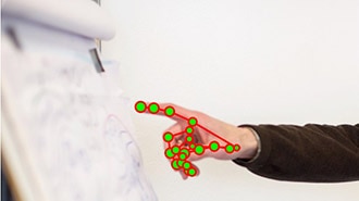
Control the RedBot wirelessly based on the movement of your hand using an accelerometer and XBees!
To follow along with this tutorial, you will need the following materials. You may not need everything though depending on what you have. Add it to your cart, read through the guide, and adjust the cart as necessary.
You will need wire, wire strippers, a soldering iron, solder, and general soldering accessories.
Glove
Scissors
Non-Conductive Thread
If you aren’t familiar with the following concepts, we recommend checking out these tutorials before continuing. This tutorial continues on from the Wireless Glove Controller and Wireless RC Robot with Arduino and XBees tutorials. Make sure to check through guides.
Build a wireless glove controller with Arduinos to trigger an LED using XBees!
Wireless RC Robot with Arduino and XBees
In this tutorial, we will expand on the SIK for RedBot to control the robot wirelessly with XBee radios! We'll explore a different microcontroller and wirelessly control the RedBot at a distance.
Accelerometer Basics: A quick introduction to accelerometers, how they work, and why they're used.
XBee Shield Hookup Guide: How to get started with an XBee Shield and Explorer. Create a remote-control Arduino!
Assembly Guide for RedBot with Shadow Chassis: Assembly Guide for the RedBot Kit. This tutorial includes extra parts to follow to go along with the RedBot Inventor's Kit tutorial.
Exploring XBees and XCTU: How to set up an XBee using your computer, the X-CTU software, and an XBee Explorer interface board.
Experiment Guide for RedBot with Shadow Chassis: This Experiment Guide offers nine experiments to get you started with the SparkFun RedBot. This guide is designed for those who are familiar with our SparkFun Inventor's Kit and want to take their robotics knowledge to the next level.
The connection for this project should be the same as the initial circuit. The only differences are the connections for the accelerometer and analog reference pin as shown in the diagram below.
Since the ADXL335 requires 3.3V, we'll need to connect the VCC pin to 3.3V. To complete the connection for power, you will need to connect GND to GND. Then for the x, y, and z pins, you'll need to connect them to pin 2, 1, and 0, respectively.
Note: An analog accelerometer was chosen for simplicity. However, any digital accelerometer (like the MMA8452Q included in the RedBot kit) can work with the setup as long as you adjust the connection and code to communicate with the sensor. Make sure that the accelerometer is low-G so that it is sensitive enough to detect motion.
Since the ADXL335 is 3.3V, we'll need to connect the Arduino's AREF pin to the 3.3V pin. This will configure the reference voltage used for the analog output from the accelerometer. As a result, we can measure smaller voltages (i.e. your 3.3V output) with the best resolution on a 5V Arduino.
⚡ Warning! Make sure to check out this note from Arduino before powering and uploading code to your board!
Don’t use anything less than 0V or more than 5V for external reference voltage on the AREF pin! If you’re using an external reference on the AREF pin, you must set the analog reference to EXTERNAL before calling analogRead(). Otherwise, you will short together the active reference voltage (internally generated) and the AREF pin, possibly damaging the microcontroller on your Arduino board.
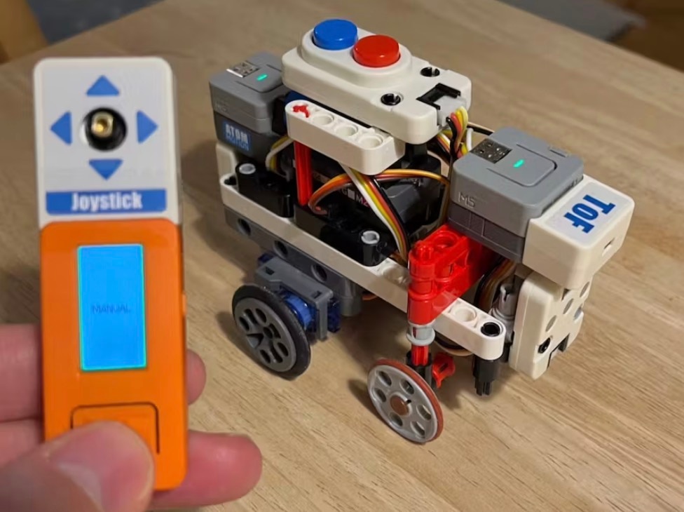
We'll assume that you have a fully assembled robot with the Shadow Chassis.
Assembly Guide for RedBot with Shadow Chassis
Assembly Guide for the RedBot Kit. This tutorial includes extra parts to follow to go along with the RedBot Inventor's Kit tutorial.
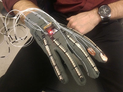
Adding on to the glove that was built in the Wireless Glove Controller tutorial, remove the tape and disconnect the braided wire from the shield. Then pull the XBee shield off the RedBoard.
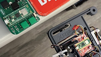
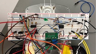
Using the circuit diagram with the accelerometer, solder the ADXL335 breakout board to the shield. In this case, female headers were used with male headers soldered on the breakout. Then strip solid core, hook-up wire and solder them between the pins. If you are following along, your board should look similar to the images below. When you are ready, stack the board back on top of the RedBoard and secure the battery.
Top View of Components Soldered on XBee Shield
Bottom View with Wires and Jumpers
Note: If you are using the XBees from the glove and RC robot tutorial, they should be the same configuration! You can move on to the next section.
To configure the XBees, we will be using the XBee Series 1 firmware. It is recommended to configure each XBee using the XBee Explorer USB.
If you have not already, check out the Starting with XCTU section under Exploring XBees and XCTU to configure your XBees.
How to set up an XBee using your computer, the X-CTU software, and an XBee Explorer interface board.
For simplicity, we will be sending commands with the XBees in transparent mode set for a point-to-point configuration. Make sure to configure each XBee with a unique MY address if there are more than two XBees in your CH and PAN ID. You will then need to adjust the DL address for each respective XBee.
Note: This example assumes you are using the latest version of the Arduino IDE on your desktop. If this is your first time using Arduino, please review our tutorial on installing the Arduino IDE.
Remember, to program your robot, you will first need to install some FTDI drivers. Follow the steps in How to Install FTDI Drivers to do so. This is also explained in the RedBot Guides.
How to install drivers for the FTDI Basic on Windows, Mac OS X, and Linux.
Note: If you have not previously installed an Arduino library, please check out our installation guide.
Make sure to install the RedBot library as explained in the RedBot Library Quick Reference. You'll also find the quick overview of the RedBot Library, classes, methods, and variables.
RedBot Library Quick Reference
Note: If you are not familiar with calibrating your accelerometer, check out this tutorial about calibrating the ADXL335.
In this part of the example, we'll have the glove send a character when the thumb and middle finger make contact. As long as the two fingers have contact, the robot will move forward, forward-left, back, or forward -right based on the orientation of your hand. When the custom button is not pressed, the buzzer will make a familiar 8-bit sound when waving your hand or "jabbing" the air. The RGB LED will light up based on the mode and orientation of the hand.
Copy the code, paste it into the Arduino IDE, select your board (Arduino/Genuino Uno), and COM port. Then upload the code to the glove.
// We'll use SoftwareSerial to communicate with the XBee:

#include <SoftwareSerial.h>

//For Atmega328P's
// XBee's DOUT (TX) is connected to pin 2 (Arduino's Software RX)
// XBee's DIN (RX) is connected to pin 3 (Arduino's Software TX)
SoftwareSerial XBee(2, 3); // RX, TX

//For Atmega2560, ATmega32U4, etc.
// XBee's DOUT (TX) is connected to pin 10 (Arduino's Software RX)
// XBee's DIN (RX) is connected to pin 11 (Arduino's Software TX)
//SoftwareSerial XBee(10, 11); // RX, TX

//set analog read pins
const int xPin = 2;//x=A2
const int yPin = 1;//y=A1
const int zPin = 0;//z=A0

//read the analog values from the accelerometer
int xRead = analogRead(xPin);
int yRead = analogRead(yPin);
int zRead = analogRead(zPin);

//LED Status Indicator
int ledR = 5;//hardware PWM
int ledG = 6;//hardware PWM
int ledB = 9; //hardware PWM

//Accelerate Button
#define ACCELERATE_BUTTON 4 // Pin used for accelerate button
const int ledPin1 = 13;  //LED on the push button

boolean current_buttonACCELERATE_State;

void setup() {
  // initialize the digital pins as an output for LEDs
  pinMode(ledPin1, OUTPUT);
  pinMode(ledR, OUTPUT);
  pinMode(ledG, OUTPUT);
  pinMode(ledB, OUTPUT);

  analogReference(EXTERNAL);//reference 3.3V since using 3.3V accelerometer

  pinMode(ACCELERATE_BUTTON, INPUT_PULLUP); // Enable pullup resistor for accelerate button D2

  // Set up both ports at 9600 baud. This value is most important
  // for the XBee. Make sure the baud rate matches the config
  // setting of your XBee.
  XBee.begin(9600);

  for (int i = 0; i < 3; i++) {
    digitalWrite(ledPin1, HIGH);
    delay(50);
    digitalWrite(ledPin1, LOW);
    delay(50);
  }
  sequenceTest();//visually initialization

  Serial.begin(9600);
  Serial.println("Wireless XBee Glove Controller Initialized");
}

void loop() {

  current_buttonACCELERATE_State = digitalRead(ACCELERATE_BUTTON);


  //Read accelerometer axes using through the ADC
  //Note: Check description at top for results based on Accelerometer Mode's Features
  xRead = analogRead(xPin);
  Serial.print("Analog xPin (A2) = ");
  Serial.println(xRead);
  yRead = analogRead(yPin);
  Serial.print("Analog yPin (A1) = ");
  Serial.println(yRead);
  zRead = analogRead(zPin);
  Serial.print("Analog zPin (A2) = ");
  Serial.println(zRead);
  Serial.println("");
  //delay(500); //slow down the print to read, adjust as necessary for testing

  if (current_buttonACCELERATE_State == LOW) {
    if (xRead < 430) {
      Serial.print("Drive Forward, xRead = ");
      Serial.println(xRead);
      Serial.println('A');

      XBee.write('A');
      greenON();
    }
    else if (xRead > 590) {
      Serial.print("Drive Backward, xRead = ");
      Serial.println(xRead);
      Serial.println('C');

      XBee.write('C');
      blueON();
    }
    else if (yRead > 590) {
      Serial.print("Drive Forward Right, yRead = ");
      Serial.println(yRead);
      Serial.println('B');

      XBee.write('B');
      cyanON();
    }
    else if (yRead < 430) {
      Serial.print("Drive Forward Left, yRead = ");
      Serial.println(yRead);
      Serial.println('D');

      XBee.write('D');
      cyanON();
    }
    else {
      Serial.println("Coast");
      Serial.println('J');

      XBee.write('J');
      magentaON();
    }

  }
  else {
    if (xRead > 670) {

      Serial.println("Coin Sound, xRead = ");
      Serial.println(xRead);
      Serial.println('X');

      XBee.write('X');
      allOFF();
      delay(50);
      yellowON();
      delay(50);
    }
    if (zRead < 400) {

      Serial.println("Fireball Sound, zRead = ");
      Serial.println(zRead);
      Serial.println('Y');

      XBee.write('Y');
      redON();
      delay(50);
      allOFF();
      delay(50);
      redON();
      delay(50);
      allOFF();
      delay(50);

    }
    else {
      Serial.println("Stop");
      Serial.println('K');

      XBee.write('K');
      redON();
      delay(750);
    }
  }

  //show that we are sending a character
  digitalWrite(ledPin1, HIGH);
  delay(50);
  digitalWrite(ledPin1, LOW);
  delay(50);
}//end loop

void allOFF() {
  analogWrite(ledR, 0);
  analogWrite(ledG, 0);
  analogWrite(ledB, 0);
}

void allON() {
  analogWrite(ledR, 150);
  analogWrite(ledG, 255);
  analogWrite(ledB, 255);
}

void redON() {
  analogWrite(ledR, 255);
  analogWrite(ledG, 0);
  analogWrite(ledB, 0);
}

void magentaON() {
  analogWrite(ledR, 150);
  analogWrite(ledG, 0);
  analogWrite(ledB, 255);
}

void blueON() {
  analogWrite(ledR, 0);
  analogWrite(ledG, 0);
  analogWrite(ledB, 255);
}

void cyanON() {
  analogWrite(ledR, 0);
  analogWrite(ledG, 255);
  analogWrite(ledB, 255);
}

void greenON() {
  analogWrite(ledR, 0);
  analogWrite(ledG, 255);
  analogWrite(ledB, 0);
}

void yellowON() {
  analogWrite(ledR, 150);
  analogWrite(ledG, 255);
  analogWrite(ledB, 0);
}

void sequenceTest() {
  redON();
  delay(50);
  magentaON();
  delay(50);
  blueON();
  delay(50);
  cyanON();
  delay(50);
  greenON();
  delay(50);
  yellowON();
  delay(50);
  allON();
  delay(50);
  allOFF();
  delay(50);
}
The commands to control the RedBot should be the same code that was used in the last example of the Wireless RC Robot with Arduino and XBees tutorial. Head over to Experiment 4.2: Adding Audio with the ATmega328P to upload code to the RedBot mainboard if you have not already.
Experiment 4: Wirelessly Triggering Audio
After uploading, touch the metal snap pins between your thumb and middle finger to move the robot forward-left, forward, forward-right, or backward. The RGB LED will light up based on the orientation of your hand. Separate your fingers and punch the air as if there is a question mark block above you to hear coin sound effect! Wave your hand to see if you can make a fireball sound effect!