Mfr Part # DFR0315
SENSOR OPTICAL -
DFRobot
Robots use a vast array of sensors to perceive the world, but for mobile robots, one of the toughest challenges is simultaneously tracking their surroundings and maintaining an accurate record of their own position. This complex process is known as Simultaneous Localization and Mapping, or SLAM. Fortunately, there is a sensor technology perfectly suited for this task, and today we're going to take a deep dive into LiDAR.

LiDAR stands for Light Detection and Ranging. It's the technology found in everything from self-driving cars and sophisticated drones to consumer robot vacuums. Professional-grade LiDAR has even been mounted on airplanes for geological surveys and rainforest mapping. Even though professional LiDAR can be very expensive, hobby-level devices like the one I'll explore today make the technology highly accessible, and you'll understand how it works and how to integrate it into your own projects.

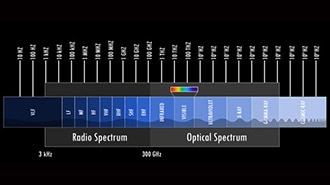
LiDAR is actually really similar to how radar works, but instead of sending out radio waves and waiting for them to bounce back, it sends out light signals. Let me show you what I mean with a little example. I'm going to stand right in the middle of my workshop, and “emit” a laser beam (measure with my tape measure) until it hits something (like the wall) and “reflects” back. Because I have a smart processor on board (my brain), I can measure that (I’m just reading the tape measure), and it is 1.67 meters away. However, just shooting out a single laser beam and waiting for it to return gives us only one data point. If I want to map the world around me, I need to have the laser beam spinning. I'm going to spin in a circle and keep taking measurements until I've collected all the points around me in a 360° circle. The more measurements I take as I spin around, the higher the resolution of my image will be. So that's why most LiDAR devices have a spinning component. Those light pulses are constantly measured as the device spins, which gives you a full 360° picture of your surroundings.


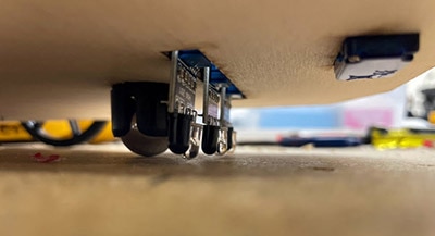
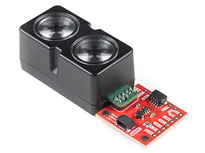
If you've done any robotics at all, you're probably familiar with an ultrasonic sensor and an optical reflective sensor. What's the difference between these and LiDAR? This ultrasonic sensor works very similarly. It sends out ultrasonic sound waves and detects the reflections. You can get fairly accurate distance measurements with an ultrasonic sensor, but it has some downsides. They don't work very well in noisy environments, and you don't get very good resolution either. Plus, if you want to get a sense of your entire surroundings, you'd have to put this on a spinning platform. It's the same story with these optical reflective sensors. These send pulses of IR light and measure the reflections, but with these sensors, you can't even measure distance. The only thing you can do with these is detect whether or not something is present. This optical reflective sensor can really only sense out to about 5cm. This ultrasonic sensor can't even measure anything closer than 30cm. On the other hand, this LiDAR device can measure up to 12m and up to 8000 samples per second. So, for applications that require a detailed view of the surroundings, LiDAR is really the best sensor technology.


There are many hobby-level LiDAR sensors out there, but the one I'm using is the RPLiDAR A1M8. You can purchase this device on the DigiKey website, and it's a great starting point. The first thing I noticed when I looked at the device was that it uses a regular DC motor. The motor uses a rubber band and pulleys to rotate the sensor. If you look closely, you'll see a small laser module embedded, and then on the other side, there’s the optical sensor that measures the reflections. A cool thing about this device is that it doesn't use a slip ring to transfer the power and communication to the sensor module. It actually uses wireless communication so that the unit can last much longer. If it used a slip ring, it would wear out so much quicker. There are two connectors on the bottom. One is for UART serial communication, and the other is for motor control. Before I attach this LiDAR sensor to my computer, I want to mount it on a stand, so I designed and 3D printed an enclosure. The nice thing about this enclosure is that it covers all the moving parts and provides a bit more protection. My hope is that by mounting this LiDAR sensor on this stand, I'll get a much clearer picture of the walls of my workshop.


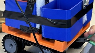
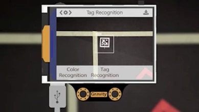
In preparation for taking measurements with this sensor, I've downloaded and installed SlamTec RoboStudio, which is the manufacturer's demo software. First, I need to go into the LiDAR sensors area and add a manual connection to this LiDAR sensor by selecting my COM port. Once I hit connect, I'm hoping that it starts working. At the center of the display is a polar coordinate system that shows the angle and amplitude, or, in this case, the distance, of our measurements. There's a little play button at the bottom of the screen. I’ll send that command and see what happens. It looks like I've got some red lines, and it looks like I see a 90° corner exactly where I would expect here in this corner, behind me. So, I think the LiDAR sensor is actually working. We're getting good data out of it, which is really exciting. You can tell that the first wall is very smooth, but the wall adjacent to it has the blue bins and the red bins that kind of give those jagged edges here on the graph. Now let's see what happens if I put something in front of the sensor, like my hand. I can see a tiny red line. That is my hand. Let's see if I can see my body. I'm going to stand really close to it, and then I'm going to move further back. Hopefully, there's a little red line there that is moving forward and backward. This demo is super cool, and it gets me excited about using this sensor in future projects.


Speaking of using this in a project, there are a couple of different options. The website suggests using the Software Development Kit (SDK) in your projects, but for me, and the simple things I want to do, I'm going to try to read the serial UART output from the controller. You might think I should just open the Arduino IDE and use it to talk to this device, but there's a catch. This LiDAR device only responds to hex commands and not ASCII commands. The Arduino IDE can only send ASCII. I found a serial terminal program that can send hex commands to the device, and hopefully, once I get it all set up, I can read that measurement data. The first thing I need to do is connect to the device at a baud rate of 115200 and select the correct COM port. Next, I need to send the start scan command, which is hex A520. Once I send those numbers, I get a response. That's a good sign. To capture the measurement data, I need this sensor module to rotate, and the motor control pin for this module is connected to the DTR pin. In the software, I can actually clear that pin with a button, which sets it to zero, and that turns on the motor. Once I got the motor spinning, it looked like the measurement data started streaming over the COM port. This is great news because, if I want to use this in a project, all I have to do is have my microcontroller read and parse the data, then pull out the angle and distance measurements.


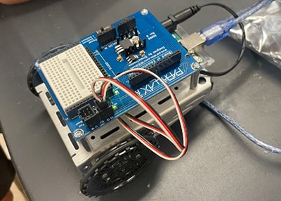
Speaking of upcoming projects, I need to build something with this LiDAR sensor. That's what I'm going to be working on next. Maybe I'll even mount this thing on the XRP platform and do something really cool.

Whether you're a hobbyist, a maker, or an engineer, these LiDAR sensors really open up a whole world of possibilities. If you want to try this out for yourself, go check out the product page on the DigiKey website. While you're there, you should explore the other LiDAR sensor types they offer.